DIN 3015 fastening clamps make assembly effective and economical, and guarantee defined pipe conduction. The system can be applied to multiple areas and sectors of industrial activity, but to do so it is essential to understand the product’s range, composition, and characteristics.
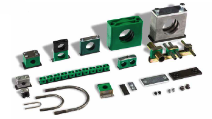

The clamp is made up of two identical halves that clamp the pipe, cable, or hose, and maintain the exterior measurement of the object that must be clamped. The clamp’s material will depend on the circuit’s pressure, temperature, and the location where it is installed.
The inner face of the clamp is manufactured with ribs or with a smooth surface. In this sense, clamps with ribs offer dampening against jolts and vibrations and absorb forces that act in the direction of the pipe’s axis, while clamps with a smooth inner surface are recommended for fastening flexible pipes and cables.
MATERIALS
Series A, B, and C clamps have metal parts: the weld plates are phosphated while upper plates are bichromated. All steel parts can also be supplied in AISI316Ti (1.4571) stainless steel.
The materials used to manufacture the body of the clamps are:
– Polypropylene: green colour
– Polyamide 6: black colour
– Solid rubber: black colour
– Aluminium
IDENTIFICATION CODE
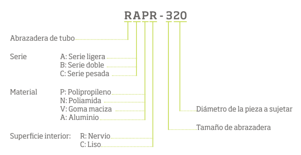
The ordering codes for half clamps, as well as for full clamps, include the designation of the series, the material name, and the inner surface.
- Polypropylene: RAPR (green colour). Soft interior: RAPG
- Polyamide 6: RANR (black colour). Soft interior: RANG
- Solid Rubber: RAVR (black colour). Soft interior: RAVG
- Aluminium: RAAR
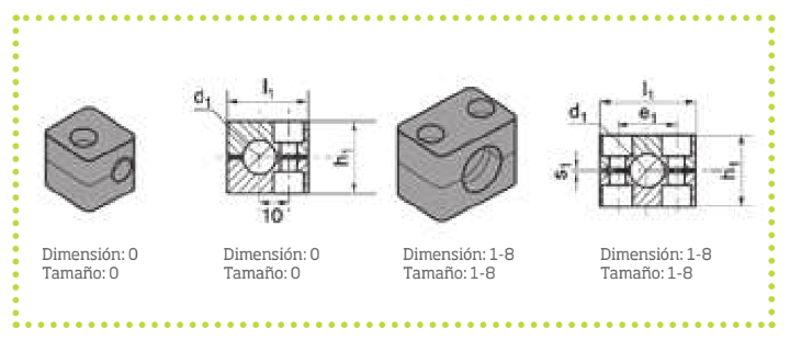
CLASSIFICATION AND SIZES AVAILABLE
LIGHT SERIES (A SERIES) DIN 3015 CLAMPS
– Polypropylene (P): Size from 1 to 8
– Polyamide (N): Size from 1 to 8
– Aluminium (A): Size from 1 to 6
DOUBLE SERIES (B SERIES) DIN 3015 CLAMPS
– Size from 1 to 5
HEAVY SERIES (C SERIES) DIN 3015 CLAMPS
– Polypropylene (P): Size from 1 to 9
– Polyamide (N): Size from 1 to 8
– Aluminium (A): Size from 1 to 8
DESCRIPTION AND ASSEMBLY OPTIONS
RAW MATERIAL
Pipe clamps are produced mainly from thermoplastic rubber.
ADVANTAGES
They offer significant improvements in terms of noise dampening and vibration behaviour.
THE IMPORTANCE OF ENSURING THE QUALITY OF MATERIAL USED
Using only quality materials, we guarantee:
- Reduced vibrations with a subsequent reduction in noise
- Resistance to the elements and ageing
- Deterioration through use is avoided, given the elasticity of the material used
- Resistance against a great number of chemical substances
- A wide margin of application with regard to ranges of temperatures
ASSEMBLY
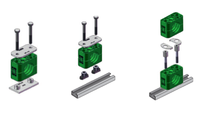
Assembly on weld plates
Weld theweld plates on a base that is suited for the load. Pay attention to the orientation of the clamps.
Restrain the lower half of the clamp on theweld plate, insert the pipe, place the second half of the clamp on top, and tighten it with the bolts. Pay attention to the pre-tension (the clamp halves should not be in contact after assembly).
Never weld with the plastic clamp already placed!
Assembly on pipe holder ducts
There are 4 different heights with pipe holder ducts, and 1 or 2 m long pieces are usually provided.
Weld the pipe holder duct or tighten it with an angular fastening piece.
Insert the pipe holder duct nuts into the duct and turn them as far as possible. In the heavy construction series, you should only insert them.
Restrain the lower half of the clamp on the duct pipe holder bolts, insert the pipe, place the second half of the clamp, and fasten it with the bolts. Before tightening the bolts, the clamp can be positioned. Pay attention to the pre-tension (the clamp halves should not be in contact after assembly).
Overlaid assembly
The clamps allow for assembly with various clamps of the same construction size, but also different pipe diameters, with one on top of the other. This overlaid assembly is carried out with special bolts that protect against torsion through safety plates.
Restrain the lower half of the clamp on theweld plate, insert the pipe, place the second half of the clamp on top, and tighten it with the bolts. This bolt extends out over the upper half of the clamp. By placing a guard plate on top, possible torsion from this bolt is avoided.
SPECIFIED TORQUE FOR SCREWS AND PIPE CLAMPING AXIAL FORCES
The values for the specified torque for screws and pipe clamping axial forces refer to assembly with cover plates and exterior hexagonal bolts according to the ISO standard 4014/4017 (DIN 931/933).
The pipe clamping axial force (according to DIN 3015, part 10) is an average value that is determined based on three trials at 23°C with a St 37 steel pipe according to DIN 2448, for which the existence of friction from adherence is presumed. When a load from the clamp is noted in the axial direction of the pipe with the test force (F) indicated, the tube should not slide inside the clamp.
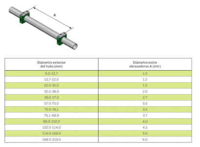
RECOMMENDED DISTANCES BETWEEN CLAMPS
The distances assigned to the various outer pipe diameters are considered to be standard values for the static load.
.
For more information on the range of Clamp products available at LEKU-ONA, contact us at: | T +34 943 74 34 50 | E leku-ona@leku-ona.com


 sending...